THERMAL FRONT PARAMETER
by ZAMG
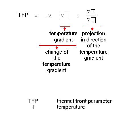
The first factor describes the change of the temperature gradient, the second factor describes the projection of the first term in the direction of the temperature gradient.
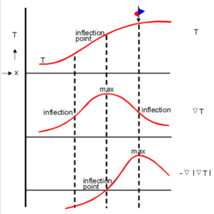
There is a clear relationship between the TFP as frontal analysis parameter and the well-known basic front definition which fixes a Cold Front where temperature begins to fall and a Warm Front where the rise of temperature ends. This definition is identical with the maximum of the TFP as shown below.
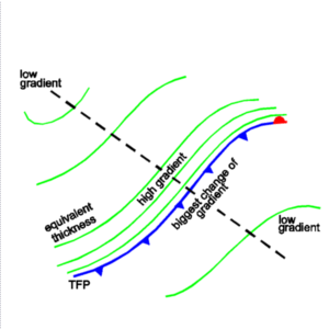
There are relationships between the thickness field and the TFP. As can be seen from the following diagram the maximum of the TFP field which is the location of the front can be found on the warm side of the zones of high thickness gradients because there the change of the thickness gradient is a maximum.
|
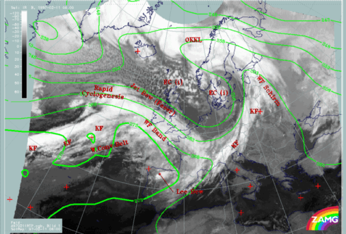
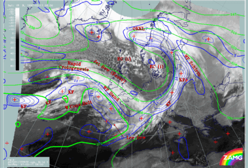
11 February 1997/06.00 UTC - Meteosat IR image; green: equivalent thickness 500/850 hPa, SatRep overlay: names of conceptual models
|
11 February 1997/06.00 UTC - Meteosat IR image; red thick: front indicator, green: equivalent thickness 500/850 hPa, blue: thermal front
parameter (TFP) 500/850 hPa, SatRep overlay: names of conceptual models
|
|
|
- A thickness crowding zone over Germany, Poland and the Baltic Sea which is to the rear of the Cold Front cloud band over Central Europe; consequently the TFP maximum line (front indicator) is close to the rear of the cloudiness. This is a situation which can often be observed in Kata Cold Fronts (although in this special case other parameters possibly contradict).
- A thickness crowding zone from the Atlantic across the British Isles to France which coincides with warm front cloud bands. Consequently the TFP maximum and the front indicator are close to the warm edge of the frontal zone which is to the rear of a Warm Front. Such situations are typical of Ana Warm Fronts.
- More indistinct is the situation with the Atlantic Cold Front because there is a broad zone of a relatively equal thickness gradient behind the front. Two areas of maximal changes of the temperature gradient are computed: one within the Cold Front cloud band and a second one in the area of the cloud spiral of the Rapid Cyclogenesis. The analysis of the cloud spiral as an Occlusion is because of the overall situation and is not supported by the thickness configuration.

